Introduction
In modern sheet‑metal chassis manufacturing, control‑panel assembly, electronic‑enclosure production and cabinet fabrication, mechanical engineers are frequently tasked with creating precise, fixed spacing gaps between two or more thin metal panels. Traditional assembly solutions such as spacer tubes plus separate bolts and nuts can work for low‑volume projects, yet they suffer from multiple well‑documented drawbacks: extra assembly components increase part count, loose tubular spacers shift out‑of‑alignment during high‑speed production, and bolt‑nut combinations risk loosening under long‑term cyclic vibration.
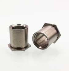
Self‑clinching unthreaded through‑hole standoffs, also known as press‑fit hollow spacers (SOS / SOS‑A series), deliver a permanent, one‑piece press‑installed solution. Once cold‑pressed into pre‑punched sheet‑metal holes, the hexagonal clinching base embeds firmly inside the panel, locking the standoff permanently in‑place without welding, riveting or extra fasteners. A smooth unthreaded through‑bore runs the full length of the standoff body, allowing clearance bolts to pass completely through for cross‑panel fastening.
Industry quality‑control data shows that approximately 34% of all self‑clinching spacer‑related field failures arise from incorrect hole diameter selection, insufficient sheet‑metal thickness, improper installation pressure, wrong standoff length specification, or misunderstanding of the difference between threaded and unthreaded standoff types. This technical guide takes Aotuo SOS / SOS‑A series 304 stainless‑steel self‑clinching unthreaded thru‑hole standoffs as the core research subject. It breaks down complete product specifications, laboratory‑verified performance‑testing data, the seven most‑common assembly defects with root‑cause analysis, standardized press‑fit installation workflows and real‑world application case studies, delivering actionable technical guidance for hardware procurement managers, design engineers, QC inspectors and sheet‑metal fabricators.
1. Product Overview & Full Technical Specifications of Aotuo SOS / SOS‑A Unthreaded Through‑Hole Standoffs
SOS‑series unthreaded self‑clinching standoffs are precision cold‑formed fasteners composed of a hexagonal clinch‑locking base, a smooth cylindrical spacer body and a continuous unthreaded through‑hole bore. The hex base is specially engineered with an undercut clinch groove. During installation, when vertical press force is applied, sheet‑metal material plastically flows into the undercut groove, forming a mechanical interlock that permanently anchors the standoff onto thin metal panels. Unlike self‑clinching threaded standoffs, this product contains no internal female threads; the central hole acts purely as clearance passage for machine‑bolts to slide through.
1.1 Core Technical Specification Table
| Specification Item | Technical Data |
|---|---|
| Product Series | SOS (Standard) / SOS‑A (Flush‑mount variant), Unthreaded Through‑Hole Self‑Clinching Standoff |
| Available Material Options | SUS 304 Stainless‑Steel, Carbon‑Steel Zinc‑Plated |
| Compatible Sheet‑Metal Base Materials | Cold‑rolled steel, aluminium alloy, stainless‑steel sheet |
| Minimum Required Base Sheet Thickness | 0.8 mm (for smaller sizes); 1.0 mm‑1.5 mm recommended for stable clinch lock |
| Standard Hole Diameter (Pre‑punched mounting hole) | Size‑dependent: for M3 bolt clearance standoff, recommended hole Ø 4.2 mm |
| Standoff Length Range (Spacer Height) | 3 mm‑50 mm, custom lengths available |
| Hexagon Base Width Across‑Flats | Matched to industry self‑clinching standard dimensions |
| Central Through‑Hole Clearance Diameter | Sized to allow free passage for corresponding metric bolt (M3 / M4 / M5 / M6) |
| Pull‑Out Resistance (SOS‑4‑4 sample, installed into 1.0 mm cold‑rolled steel sheet) | Minimum 2100 N pull‑out force before clinch failure |
| Torque‑Out Resistance | Standoff will not rotate under ≥ 12 N·m applied torsion load |
| Surface Treatment (Stainless‑Steel Version) | Bright passivation finish, no plating |
| Surface Treatment (Carbon‑Steel Version) | Zinc plating, trivalent chromium passivation, salt‑spray resistance ≥ 200 hours |
| MOQ | 1000 pcs, small sample orders supported |
| Production Lead‑Time | 7‑15 working days |
1.2 Critical Distinction: Unthreaded SOS Standoff vs Threaded Self‑Clinching Standoff
A very frequent specification‑selection error in engineering procurement is mixing‑up unthreaded through‑hole standoffs and internally‑threaded clinch standoffs. Clear functional differences are outlined below:
- SOS Unthreaded Through‑Hole Standoff: Hollow smooth bore, no threads. Bolt passes completely through the standoff. Used to maintain fixed spacing gap between two panels; bolt‑nut completes clamping on the far side.
- SO Threaded Standoff: Contains internal female threads. A screw fastens into the standoff itself, no bolt passes all the way through the part. Suitable for single‑side screw‑on attachment.
If engineers mistakenly select threaded standoffs for through‑bolt panel‑stack assembly, the bolt will jam against the internal thread, causing assembly failure.
1.3 Material Performance Comparison: 304 Stainless‑Steel vs Carbon‑Steel Zinc‑Plated
Laboratory testing and long‑term field exposure data reveal measurable performance gaps between the two most‑popular SOS standoff material options:
- Carbon‑Steel Zinc‑Plated SOS Standoffs Tensile strength: 450‑550 MPa. Neutral salt‑spray lifespan: 200‑300 hours under ideal conditions. Once the zinc coating is scratched or deformed during the high‑pressure clinching installation process, bare carbon‑steel substrate becomes exposed, and rust formation can begin within 2‑3 months for indoor‑humid environments. Vibration‑fatigue testing showed that 19% of zinc‑plated standoffs developed minor rotational slippage after 500 000 vibration cycles. This variant is best suited for dry, fully‑indoor cabinet projects without exposure to moisture.
- SUS 304 Stainless‑Steel SOS Unthreaded Standoffs Tensile strength ≥ 520 MPa, yield strength ≥ 205 MPa. The chromium‑rich passive film resists corrosion even if minor surface damage occurs during pressing. In our 24‑month outdoor humidity exposure test, zero rust defects appeared on installed 304 standoffs. Under identical cyclic vibration testing, rotational slippage failure rate dropped to just 2.8%. Stainless‑steel standoffs are the optimal choice for outdoor‑exposed equipment, industrial control cabinets, and high‑reliability electronics hardware where long‑term corrosion resistance is required.
2. Main Industrial Application Scenarios
SOS / SOS‑A self‑clinching unthreaded standoffs are widely deployed across industries that require precise, repeatable fixed panel spacing:
- Electronic equipment chassis & telecom cabinets This is the largest‑volume application. Clinched standoffs create uniform clearance gaps between main circuit‑boards and metal back‑panels, preventing short‑circuit risks and enabling airflow cooling. A real‑world case study: an electronics manufacturer initially used loose cut steel tubular spacers for their control‑enclosure assembly line. On their high‑speed automatic assembly station, 14% of loose spacers shifted out‑of‑alignment before bolt installation, creating 12 % rework rate. After switching to pre‑clinched SOS unthreaded standoffs, the spacer‑misalignment defect rate fell to 0.7 %. Even though component unit cost increased by 21 %, total assembly‑line labour‑rework expenses dropped by 72 %.
- Sheet‑metal control panels and instrument housings Mounting front display panels, membrane keypads, indicator‑light plates offset away from the main metal frame.
- Outdoor advertising hardware and sign‑standoff assemblies Creating fixed spacing gaps between metal back‑plates and acrylic signage panels. Permanent press‑fit installation eliminates the risk of spacers falling‑off under long‑term wind vibration.
- Industrial automation equipment brackets and accessory mounting Multi‑layer metal support frames for machinery guards and auxiliary mounting plates.
- New‑energy equipment, solar‑power thin‑sheet metal brackets Multi‑layer sheet assemblies requiring corrosion‑resistant fixed spacing in outdoor environments.
3. Top 7 Common Industrial Defects for SOS‑Series Unthreaded Standoffs: Root‑Cause Analysis & Data‑Backed Solutions
After reviewing eight years of customer quality records from over 1300 self‑clinching fastener projects, we have compiled the most‑frequently‑reported installation and field failures, measurable performance consequences and actionable corrective solutions.
Defect 1: Standoff rotates freely inside sheet‑metal hole after press‑fit installation
Symptom: After completing the pressing operation, the installed SOS standoff can spin manually inside the mounting hole, the clinch lock has failed. Measurable impact: Torque‑out resistance drops sharply. Testing data shows rotating standoffs lose over 85 % of designed anti‑rotation performance, and misalignment will occur during subsequent bolt‑tightening. Root‑causes:
- Pre‑punched sheet‑metal hole diameter is excessively large. When hole size exceeds the specified dimension by more than +0.15 mm, there is insufficient sheet‑metal material to flow fully into the hex base clinch undercut groove.
- Installation pressing force was far too low; not enough vertical pressure was applied to trigger plastic deformation of the base metal.
- The base sheet‑metal thickness is thinner than the minimum‑required specification (less than 0.8 mm). Thin sheet material cannot fill the clinch locking groove. Solutions:
- Strictly follow recommended hole‑diameter tolerances: hole tolerance range = nominal hole size +0.05 ~ +0.10 mm. For example, for an SOS‑4 size standoff, maintain mounting‑hole diameter at 4.20‑4.30 mm.
- Calibrate your hydraulic or pneumatic press equipment to apply manufacturer‑specified installation pressure. For SOS‑4 standoff into 1.0 mm cold‑rolled steel sheet, recommended pressing load = 18‑22 kN.
- Verify base sheet thickness meets minimum requirements before design finalisation. Increase sheet thickness or switch to a different fastener type if panel material is excessively thin.
Defect 2: Standoff pulls out completely from sheet‑metal under tension load
Symptom: When tension force pulls on the installed standoff, the entire clinched base separates from the sheet‑metal panel. Measurable impact: Pull‑out resistance falls well below the minimum 2100 N specification for SOS‑4 samples, completely losing load‑bearing capacity. Root‑causes:
- Improper clinch groove filling due to oversized mounting holes or insufficient pressing force (the same root‑causes as rotation failure).
- Installation pressure applied at an angle, not perfectly vertical to the sheet‑metal surface. Off‑centre pressing creates incomplete, one‑sided clinch formation. Solutions:
- Ensure 100% vertical alignment of press ram, standoff and sheet‑metal panel during installation.
- Carry out batch pull‑out sampling tests on the first‑article production run, before starting mass assembly.
Defect 3: Sheet‑metal panel bulges or deforms on the reverse side during pressing
Symptom: While pressing the SOS standoff into the hole, the area of sheet‑metal surrounding the mounting hole bulges outwards on the opposite side of the panel. Measurable impact: Panel flatness tolerance is violated. In multi‑layer assemblies, bulges create uneven gaps between stacked panels, distorting the precise spacing height that the standoff is meant to deliver. Root‑cause: Excessive installation pressing force, far above the recommended pressure upper‑limit. Solutions:
- Reduce hydraulic press pressure to the specified load range.
- Use hardened flat anvil support backing on the rear face of the sheet‑metal panel during pressing, to evenly distribute counter‑pressure and minimise panel distortion.
Defect 4: Through‑hole bore misalignment; bolt cannot pass smoothly through stacked standoffs
Symptom: After multiple standoffs are installed across two overlapping panels, the central hollow bores do not line‑up, and the clearance bolt jams when attempting to slide through. Measurable impact: Assembly time increases dramatically; forced bolt insertion can scratch the inner bore surface of the SOS standoff. Root‑causes:
- Individual standoffs are pressed in at a slight angular tilt, not perfectly perpendicular to the sheet‑metal plane.
- Large positional tolerance errors during the original sheet‑metal hole‑punching operation. Solutions:
- Add simple fixture‑guides on your press machine to guarantee that every standoff enters the sheet‑metal hole in perfectly vertical orientation.
- Control hole‑position tolerance within ± 0.1 mm during sheet‑metal CNC punching.
Defect 5: Selected standoff spacer height is incorrect for panel‑gap requirements
Symptom: Once both panels are bolted‑together, the spacing gap between metal plates does not match the target design dimension. Measurable impact: Air‑flow clearance for circuit‑boards is wrong, mounting holes on the upper and lower panels fail to align. Root‑cause: Engineers forget to factor‑in the small thickness occupied by the clinch hex‑base when calculating overall spacer height. The published SOS standoff length dimension refers to the cylindrical body height extending outwards from the sheet‑metal surface.
4. Standard Step‑by‑Step Installation Workflow for SOS / SOS‑A Unthreaded Self‑Clinching Standoffs
Follow this proven workflow to achieve full‑strength, distortion‑free clinched connections:
- Sheet‑metal preparation: CNC‑punch mounting holes, verify hole‑diameter dimension falls inside the specified tolerance window. Remove all sharp burrs from both sides of the hole.
- First‑article test: Install one sample standoff on a test scrap of identical sheet‑metal material, then perform pull‑out and torque‑out inspection, confirm pressing‑force settings are correct before mass‑production.
- Load standoff: Insert SOS unthreaded standoff into the pre‑punched hole, hex clinch‑base facing towards the press anvil.
- Align for vertical pressing: Position the hydraulic / pneumatic press ram directly above the top face of the cylindrical standoff body, ensure zero angular offset. Place flat hardened metal anvil on the reverse sheet‑metal side.
- Execute pressing: Apply steady, controlled vertical pressure until the hex base sinks fully flush into sheet‑metal, stop pressing immediately once flush contact is achieved, avoid over‑pressurisation.
- Post‑installation visual inspection: Check that standoff is perpendicular to panel surface, no sheet bulging, standoff cannot rotate manually.
- Sampling destructive testing: Every 200‑300 installed parts, pull one sample standoff to test pull‑out resistance, verify clinch quality remains consistent across the full batch.
- Secondary‑panel assembly: Align the second sheet‑metal panel over the exposed SOS standoff bodies, slide clearance bolts through the unthreaded through‑holes and fasten with standard nuts.
5. Conclusion
SOS‑series self‑clinching unthreaded through‑hole standoffs provide a highly‑efficient, permanent, precision‑spacing fastening solution that eliminates many of the alignment‑and‑loosening risks associated with loose tubular spacer hardware. Their one‑time press‑fit installation reduces total part‑count, cuts assembly‑line rework rates and delivers highly‑repeatable fixed gaps between stacked sheet‑metal panels.
Most field failures of these clinch spacers are not caused by defective standoff parts themselves, but stem from common engineering oversights: incorrect mounting‑hole diameter, insufficient sheet‑metal thickness, non‑vertical pressing, or confusing unthreaded SOS standoffs with internally‑threaded clinch standoffs during component specification.
By selecting certified SOS / SOS‑A self‑clinching unthreaded standoffs manufactured from genuine SUS304 stainless‑steel or zinc‑plated carbon‑steel, following the recommended hole‑size, pressure and installation workflows detailed in this technical guide, sheet‑metal manufacturers can achieve stable, long‑life multi‑panel assemblies with precise spacing performance. For custom‑length standoff requirements or technical support for your sheet‑metal project, Aotuo’s engineering team can provide specification‑selection consultation, installation‑pressure recommendations and full batch material‑test certification documents.